Shopping Cart
There are no more items in your cart
- ELECTRICAL NEWS
- 0 likes
- 315 views
- 0 comments
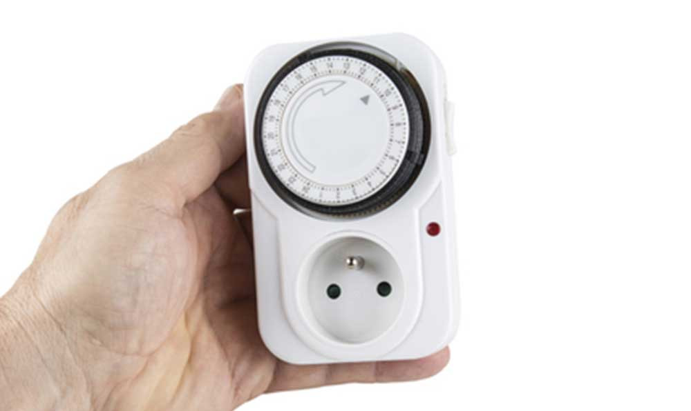
Installation guide for a time switch
Time switches are innovative devices designed to automatically regulate the turning on and off of electronic devices. Simply set your preferred time and day. These devices come in various forms, including mechanical, digital and astronomical models, to adapt to every need.
Connection Diagram of a Time Switch
To connect a time switch, the contact used is generally changeover. This means that the terminals to be used depend on the type of switch and the desired function. Terminals 1,2,3 and 5,6,7 are commonly used, as shown in the illustrative figure. An external power source, connected to terminals L and N, is essential to guarantee the operation of the switch.
The Advantages of Multi-Channel Time Switches
A significant innovation in the world of time switches is represented by multi-channel models. These devices allow you to program different times simultaneously, thanks to the presence of separate channels (such as channel "A", using terminals 1,2,3 and channel "B", with terminals 5,6,7). This functionality makes multi-channel time switches particularly versatile and suitable for managing multiple devices or systems at different times.
- Easy and flexible setting of on/off times
- Variety of models to satisfy every need: mechanical, digital, and astronomical
- Possibility to program multiple times with multi-channel switches
Thanks to this guide, installing a time switch will be a simple and clear process. Whether for the management of external lighting, for the control of security systems, or for the automation of other electronic devices, a time switch represents an efficient solution for saving time and energy.
Time switch installation guide
The time switch is a useful tool for controlling the automatic turning on and off of electrical devices. Let's see together how to proceed with the installation.
Identifying links
On the time switch there are various inputs marked with different symbols: an N which represents the neutral, and L1 and L2which are the two current lines. It is essential to correctly identify the neutral and the line serving the device to be connected.
Cable colors and their meaning
- The line cable usually has a blue color.
- The ground cable appears yellow and green.
Installation procedure
After determining the correct connections, it's time to proceed with the actual installation:
- Cut the wires and leave the copper end free.
- Insert the neutral into the terminal marked with N and the line into the L terminal.
- Add a thread "line" from the hole marked L to hole 1.
- Connect the other end of the "line" wire into hole 2.
Once all connections are complete, the time switch is ready to be tested and put into operation.
Comments (0)