Shopping Cart
There are no more items in your cart
- ELECTRICAL NEWS
- 0 likes
- 5305 views
- 0 comments
Electrical Symbols: Everything You Need to Know
Introduction to Electrical Symbols
When working on the creation or renovation of an electrical system, you often come across numerous symbols, letters and acronyms that are complicated to decipher in the various electrical diagrams. These symbols may seem difficult, but they are essential for a correct understanding and implementation of electrical systems.
Why are they important?
Electrical symbols are essential not only during installation or maintenance but also in the design phase, often carried out with software such as CAD, where the symbols are inserted directly into the drawing in DWG format. Understanding these signs is therefore crucial to working safely and compliantly.
Guide to Electrical Terms
To help you navigate these terms and symbols, we have prepared a guide that will make your task easier. Here are some key points that will allow you to decipher the electrical symbols:
- Convenience and practicality: The limited spaces within the electrical diagrams make the use of symbols and acronyms essential to indicate regulations and functions without burdening the project.
- Uniformity: The symbols adopted follow standards recognized in numerous European countries, not only in Italy, allowing international understanding.
- Warnings and controls: The symbols can indicate warnings, potential dangers or elements relating to maintenance and controls such as the ISO 9001 standard.
International differences
It is important to note that some symbols may have different meanings in the United States than in Italy, so it is essential to know the context in which they will be used.
Introduction to Electrical Systems Regulations
The standard that regulates this nomenclature is CEI 3-25 which defines the graphic signs, letters and acronyms of these systems. These acronyms are essential to identify the safety of the product you are about to use.
Identification of Products through Acronyms
The acronyms codify and provide immediate information on the safety of the electrical product. The most common ones are listed below, divided into paragraphs and used in civil or industrial systems.
Unit of measure
The standard units of measurement used to quantify and evaluate electronic and electrical quantities are fundamental for the correct functioning of systems. Here are some of the most common:
- V = Volts (electrical voltage).
- A = Ampere (current absorbed by the connected device).
- W = Watt (power absorbed).
- Va = Volt/Ampere (apparent absorbed power).
- Var = reactive power used as a parameter to evaluate power factor correction.
- ΔV = potential difference.
- C = Coulomb (amount of current carried in 1 second by 1 ampere current flow).
- °C = Degrees Celsius (temperature).
- ° F = Degrees Fahrenheit (temperature).
- Ah = Ampere hour.
- atm = atmospheres (widely used as a unit of measurement of pressure).
- Cv or Hp = horsepower.
- Emu = electromagnetic unit of measurement.
- F = Farad (electrical capacitance).
- J = Joule (unit of measurement of energy, heat and work).
- Hz = Hertz (Frequency).
- lm = Lumen (used as an indicator of light intensity).
- KWh = Kilowatt hour (counts the electricity used).
- cosφ = Power factor.
- P = Active power.
- Pq/Q = Reactive power
- Ps/S = Apparent power
- R = Electrical resistance.
- T = Electrical voltage.
- U = Potential energy.
- Z = Impedance
- P = Resistivity
- ω = Pulsation
- db = Decibel
- cd = Candle
- lx = Lux
- ma = Milliampere
- kΩ = kiloohms
Letters to Identify Materials and Equipment
According to the EC 750 and CEI 3-43 regulations, specific letters are adopted. Below are the standard letters used to identify the materials and devices used in the systems:
- A = Assemblies (amplifiers, magnetic components, printing circuits).
- B = Transducers (photoelements, measurement converters, transducers, photodiodes, pulse generators, load cells, microphones, speakers).
- C = Capacitors.
- D = Binary systems (monostable, bistable, regulation, recording).
- E = presence of more than one material not marked with a letter.
- F = Protection device (fuses, surge arresters, protection relays).
- G = Generators (rectifiers, stabilizers, alternators).
- H = Acoustic or luminous signaling devices.
- K = Control relay and power contactors.
- L = Coils and inductances.
- M = Engines.
- N = Analog systems and regulation.
- P = Measuring instruments (timers, indicators).
- Q = Devices for power circuits (disconnectors, start or stop inverters).
- R = Resistances.
- S = Devices for control circuits.
- T = Control and power transformers.
- U = Converters.
- V = Electronic tubes and semiconductors (diodes, discharge tubes, transistors).
- W = Transmission material (TV antennas, couplers).
- X = Terminals (cable lugs, connection connector, fittings).
- Y = Mechanical devices (Valves, brakes, clutches all operated by electrical current).
- Z = Other (Equalization, Transformers, limiters, filters).
Terminologies Used in Electrical Systems
To better understand systems, it is essential to know some specific terminologies. Here are some often used terms:
- Sizing = Design calculation for optimal voltage drop.
- Riser = Connection of the electrical cable from the meter to the differential switch.
- Main switch = Circuit breaker located upstream of the system. By turning off this switch the electric current will not flow through your devices.
- Light Point = Station used to control the lighting.
- Socket Point = Station used for positioning electrical plugs and sockets such as the German Schuko plug.
- Fruits = Electrical components such as electrical plates, bipolar switches, diverter switches, inverter buttons.
- Rating = Maximum endurance limit of the device or conductor.
- Built-in junction boxes = Boxes for connecting cables and other components.
- CEI 64-8 = Main regulation for civil low voltage systems.
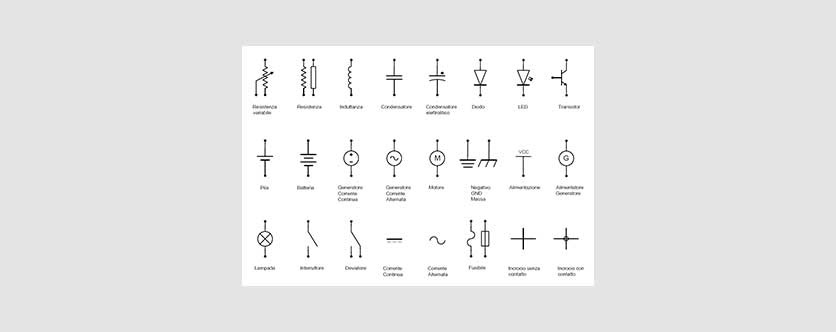
Symbols in Electrical Diagrams
The electrical diagrams visually represent the connections and functions of the systems. Generally, there are three main types of schemes:
- Functional : Simplified diagram illustrating the logic of the system.
- Assembly : Used as instructions for making the correct electrical connections between the different equipment and the correct connection to the system.
- Power : This diagram indicates the defined part of power or the motors or driving force of a system.
- Connection : In this case the type of connection of a single device or the connection between multiple devices is depicted in a much more precise and specific way.
Understanding whether the current is alternating or direct is essential to correctly interpret electrical diagrams, as the behavior of electrical flow varies greatly between the two types.
Safety Standards through Acronyms
It is important to keep in mind that there are other acronyms that indicate specific safety regulations, such as those relating to the ISO and CEI standards (e.g. ISO 9001 or CEI-64).
Comments (0)